 | |
  2024 Sistema Cheve |
Wakulla 2 Technology
Digital Wall Mapper
During the 1987 Wakulla project, and virtually all other underwater cave exploration before and after, traditional surveying techniques were used. In this approach, a knotted line is laid through the underwater tunnel and periodically tied to projections on the walls, ceiling, or floor. The surveyor's task is to count knots (spaced at approximately 3 m) between each bend, record the water depth at that point, and measure the azimuth of the line leading to the next bend. These measurements, along with estimated passage widths, heights, and floor sediment details are recorded on a slate. This procedure is time consuming and time spent at 100 m water depth carries a significant penalty in terms of the decompression requirements in the water before reaching habitat lock out depth. Having limited time also reduces the detail that can be obtained. Furthermore, each survey point has an error associated with the distance and azimuth measurements. These errors are cumulative, such that long penetrations are bound to have large survey errors at the limits of exploration. 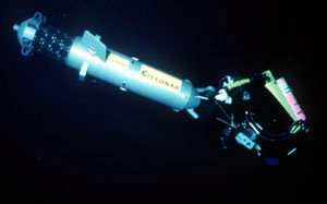 In an effort to deal with these problems, an automated digital three dimensional wall mapper (DWM) was developed especially for the Wakulla 2 project. It is designed to "latch on" to the front of a Fatman scooter. The DWM contains the following key elements: An array of 32 sonar transducers for measuring wall distances; sensors for measuring depth, water temperature and battery capacity; an Inertial Reference Unit (IRU) for computing the vehicle's position and attitude (roll, pitch, and yaw); an embedded computer to provide control, data acquisition, and a link to a host computer; a propulsion and attitude control system; and a user interface for both programming and downloading data from the DWM. The general concept is as follows. The explorer drives through the passage that is to be mapped. The onboard IRU senses the system's position in three dimensional space, together with the system's rotation about each of the three axes (roll, pitch, and heading). At a fixed interval (4 Hz minimum), the 32 sonar elements fire. The emitted sound pulses travel out radially from the mapper until they hit the passage wall, where they are reflected, and bounce back to the DWM. The time taken for the pulse to get back to the DWM is recorded, and from this the distance to the wall can be calculated. Thus four times a second, we obtain 32 equi-spaced radial readings. This information is logged by the onboard computer together with the mapper's position and attitude. At the end of the mission, this data is uploaded to a computer graphics workstation where it is processed and converted into a 3D map. The first "raw" data to appear on the computer graphics screen is a three dimensional "point cloud" showing each wall location point in its appropriate location in space. With a high enough point density it becomes easy to see the shape of the cave in 3D. One of the important aspects of the Wakulla 2 DWM technology is that every pass through a given tunnel increases the amount of information available, and hence the accuracy and resolution of the resulting map. Thus if a given portion of a tunnel is traversed ten times during the project, the radial resolution of the map under random path circumstances will be 1 part in 320, or almost 1 degree. This will allow us to map the passage in incredible detail. To put this in perspective, a typical tunnel cross section in A Tunnel (the main tunnel) is approximately 30 m in diameter. After 10 passes through the tunnel (just five actual missions, since we map both going in and returning), it will be possible resolve features on the passage walls a few tens of centimeters in size. Getting that kind of registration between separate data sets (e.g. from two distinct days of mapping missions) does not come easily. The accuracy of the map is predicated upon the ability to "lock" the guide path ("trajectory") of the vehicle to some known high accuracy control grid. This is exactly the kind of thing that the USGS does with surveys for the United States. Each state has a high resolution control grid, comprising a set of key benchmarks, into which local surveyors can tie in. The problem at Wakulla is that there is no possibility of utilizing the existing terrestrial control grid, nor any other form of alternative position determination (e.g. GPS satellites), because none of these can be received through the 100 meters of solid rock separating the DWM from the surface. What can be received, however, is a magnetic signal. Rather than trying to create the magnetic equivalent of GPS, we developed a means of establishing a subterranean control grid by using magnetically established benchmarks within the cave. These "waypoints" are registered to the surface, and hence to the USGS grid. The waypoints are established using induction radio. Computer calibrations of the drift data for the IRU showed that if we had a control point for every 500 meters of cave travelled, then the drift error in the resulting survey would be maintained within 1 meter per kilometer of travel in the East and North (i.e. longitude and latitude) dimensions. Depth is known precisely to centimeter level through the use of triplex onboard digital pressure sensors which are located on the DWM interface bus. The DWM is equipped with a lever switch on its left handle (the same one that contains the diver interface computer) which permits the operator to inform the onboard computer that a waypoint flyover has just occurred. Each waypoint, after initial location, is marked with a neutrally buoyant cylinder wrapped with prismatic micro-retroreflective material so that it will be visible for up to 100 meters in clear water. |
|
Home | |
| Copyright © 2024 U.S. Deep
Caving Team, Inc. All rights reserved. Todo el contenido tiene derechos de autor del U.S. Deep Caving Team. Todos los derechos reservados. No portion of these pages may be used for any reason without prior written authorization. | |

